An energy storage system lives or dies by its enclosure. The housing must manage heat, contain a worst-case thermal event, carry hundreds of kilograms of cells, ground high-current paths safely and survive decades of outdoor weather — all at a price a project can defend. This guide walks through thermal and fire containment, sheet-metal engineering, structural and seismic design, electrical integration, and manufacturing transparency for custom battery enclosures, using the YONGU S211 shock-proof enclosure as a production-ready reference.
Thermal Management and Fire Containment for Battery Enclosures
Thermal design starts with the heat load. Estimate it as: battery internal loss at your design C-rate (typically 1–3% of throughput for LFP at 0.5C), plus BMS, inverter and cable losses, plus solar gain on the enclosure walls. A 48V/100Ah pack discharging at 0.5C moves about 2.4 kW; at 2% internal loss that is roughly 48 W of cell heat, rising to 100–200 W total with electronics. Rule of thumb for sizing: a metal surface dissipates roughly 10 W per square meter per °C under free convection, so a 1 m² wall with a 30°C rise removes about 300 W — enough for many small-to-mid ESS. Above 200–300 W sustained, move to controlled passive design (fin ducts, heat sinks, thermal pads to the wall) or active cooling (forced air or liquid plates) rather than just a bigger box.
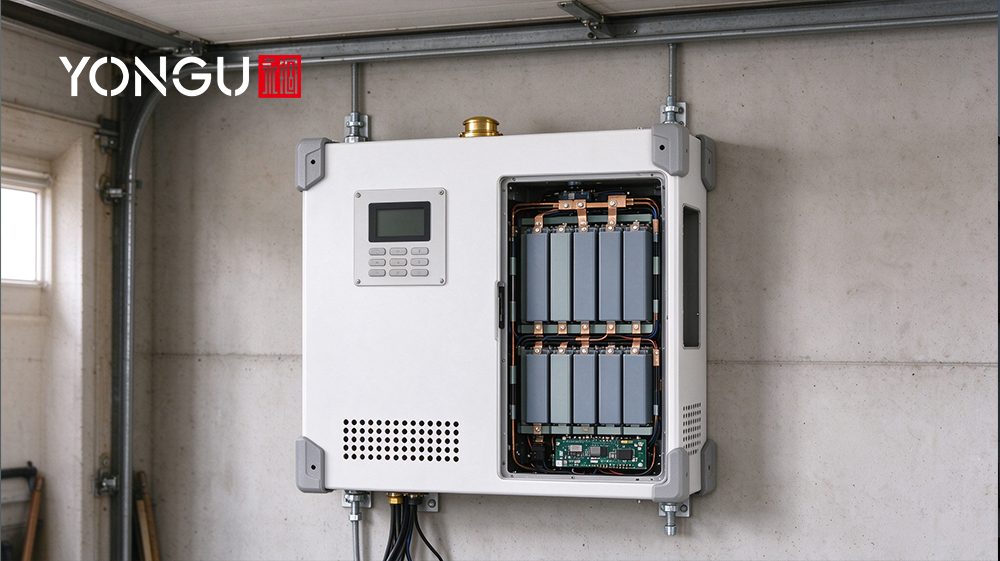
Fire containment is structural, not decorative. Design for thermal runaway propagation limits from UL 9540A: space cells or packs, add fire-retardant separators between tiers, fit pressure-relief vents that direct gas away from personnel and cable trays, and use steel or steel-lined walls where UL 9540 and NFPA 855 require a fire-rated boundary. In U.S. deployments the climate drives the seal-vs-vent trade-off: a Phoenix installation (45°C+ ambient) needs venting and possibly active cooling, while a Northeast site at -20°C needs gasketed seams and heaters to keep cells above minimum charge temperatures — an IP65 or IP66 housing with controlled breathers balances both, as covered in the IP rating guide. The YONGU energy storage enclosure and the S-series sheet-metal battery cases start from this thermal-first framework.
Sheet-Metal Engineering: Materials, Gauges, and Fabrication Details
Material choice sets the whole budget. Aluminum (5052/6061) is light, conducts heat well and anodizes or powder-coats cleanly; stainless steel (304/430) resists corrosion and fire best but costs more and adds weight; galvanized steel offers the lowest cost with good strength, at the price of lower heat conductivity and finish limits. For enclosure walls, common choices are 16 ga (≈1.5 mm) for light racks, 14 ga (≈2.0 mm) for standard outdoor cabinets, and 12 ga (≈2.7 mm) where seismic or impact duty applies. A practical bend rule: specify an inside bend radius of 1.0–1.5× material thickness for aluminum and 0.5–1.0× for steel — smaller radii crack aluminum and thin the bend wall under load.
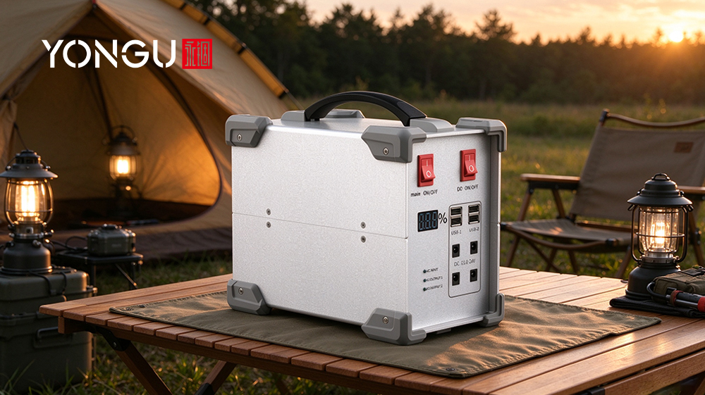
Fabrication details decide whether the box stays sealed for a decade. Specify continuous welded seams on load-bearing corners and flanged-and-sealed joints on removable panels (flange + EPDM gasket, with drainage holes at low points so water never pools inside the seam). Use PEM-style clinch nuts or weld nuts for removable covers, and keep all field-service fasteners stainless. Finishes: powder coat (60–120 µm) is the workhorse for outdoor steel and aluminum; anodize (Type II/III) suits aluminum where conductivity matters; hot-dip galvanizing protects welded steel in coastal salt. The metal fabrication process comparison details laser cutting, bending and welding trade-offs, while the S211's removable top, base and rear panels show how a production aluminum case is built for service access with protective corner guards.
Structural Integrity, Mounting, and Seismic/Vibration Considerations
Design the enclosure for the loads it will actually carry: the full battery-pack weight on the floor or rack rails, busbar and cable torque, overturning moment from wind on outdoor cabinets, and vibration from transport or machinery. A practical margin is 3× on static loads and 1.5× on dynamic ones, then check against the local building code — IBC and ASCE 7 define wind and seismic demands, and seismic Design Categories D and higher require restrained anchorage per ASCE 7 Chapter 13. Ground cabinets anchor through base plates with 4–8 anchor bolts (expansion or through-bolts for concrete); truck/trailer mounts need captive rails with rubber isolators or dampers tuned to the vehicle's vibration spectrum; rooftop or platform mounts add wind-load ties to the structure.
For field growth, design modular: a standard rack pitch (e.g., 19-inch or 23-inch EIA) lets you add battery tiers and PCS units without re-manufacturing the cabinet, and removable panels — like the S211's top and base — let installers lift cells in from above or the rear. Add leveling feet for uneven pads, lifting lugs for crane or forklift moves, and anti-tip brackets on units taller than 1.5× their footprint. For vibration-sensitive sites, choose elastomeric mounts tuned to the dominant disturbance frequency (typically 5–25 Hz for truck and trailer transport) rather than rigid brackets, and torque anchor bolts to the manufacturer's specification at installation and after the first season. The harsh-environment enclosure guide covers how wall thickness and corner guards protect structural corners in demanding installations.
Electrical Integration: Grounding, EMC, Busbar Layout and Cable Entry
Grounding comes first. Use a single-point ground (SPG) for the BMS and signal electronics, and a separate low-impedance ground path for the high-current DC circuit — bonding every panel and door with braided straps so the enclosure itself becomes a Faraday shield with <10 mΩ continuity. Multi-point grounding is reserved for the power circuit where circulating currents are controlled by design. Place a copper ground bus near the cable entry, sized for the fault current, and bond the inverter chassis, battery rack and enclosure to it.
Busbars and cables follow clear rules: run positive and negative bars in parallel with tight spacing to cancel fields, insulate to the system voltage plus margin, and keep the bar surface area or add cooling fins where current density exceeds roughly 4 A/mm² continuous. Route DC power and signal wiring in separate planes or shielded channels, and bring cables through walls at defined feedthrough points — gasketed glands or bus plates — rather than random holes, so the shield stays unbroken. Separate DC and AC compartments with a fire-rated or insulated barrier, respect creepage and clearance per the applicable UL/EN cabinet class, and fit transient suppressors at every external feedthrough. Put EMI-sensitive monitoring (thermistors, cell-voltage sensing) as far from the inverter and busbar zone as the layout allows, with twisted pairs and a local ground reference, and verify ground continuity at each annual service. The S211's front panel handles and drilled-for-purpose rear panel show how a housing can carry VGA/DVI/COM and power entries while keeping the body structurally intact; for weather-exposed builds, pair it with an IP68 battery case from the MH series when the electronics live outdoors.
Manufacturing, Lead Times, Prototyping, Testing and Cost Transparency
A custom sheet-metal enclosure moves through laser cutting, CNC bending, welding or clinching, surface prep and finishing, and final assembly. Typical lead times at a stocked fabricator: quick-turn prototype 7–14 days, small batch 2–4 weeks, production 4–8 weeks depending on finish and volume — YONGU quotes samples in 5–7 days and batch orders in 15–20 days with no minimum order quantity. Cost is driven by material, bend count and tolerance, weld length, secondary operations (inserts, gaskets, drilling), tooling and fixtures, and finish: a simple 16-ga steel box costs a fraction of a 12-ga stainless cabinet with welded seams and Class A powder coat. Laser cutting holds about ±0.1 mm and CNC bending about ±0.2 mm, so specify a flatness check on welded assemblies to keep panels interchangeable and doors aligned.
Price the BOM in blocks — sheet metal, fasteners and inserts, gaskets and seals, finish, and assembly labor — and share the CAD/STEP model so the fabricator can quote from your actual geometry. Insist on test evidence: thermal cycling, IP ingress per IEC 60529, vibration and, for ESS programs, UL 9540A thermal-runaway fire testing or an equivalent third-party report. YONGU publishes an independent IP68 test report plus ROHS and REACH certificates on the downloads page, and supports laser engraving and silk screen for serialization and certification marks on the S211 and H38 LiFePO4 solar-inverter housing. The solar controller installation guide shows a complete off-grid build path from cell to finished cabinet.
Conversion
Move your ESS project forward with YONGU's design-to-production support: send your pack layout, heat budget and site conditions for a free thermal sizing review, share CAD/STEP files for 3D model verification, and request a combined quote covering quick-turn prototype, production tooling and UL-relevant test documentation. Deliverables include a thermal calculation sheet, detailed manufacturing drawings, material and finish samples, and sample test reports; standard lead times are 5–7 days for samples and 15–20 days for batch production, with expedited options for pilot programs. Whether the cabinet lands in an outdoor utility yard, a data-center machine room or a vehicle mount, contact YONGU with your application details and get an engineered enclosure, not an off-the-shelf compromise.
FAQs
What sheet metal materials and coatings are best for outdoor battery enclosures in different U.S. climates?
Aluminum (5052/6061) with powder coat or anodize suits most regions; stainless 304/430 for coastal salt and fire-rated walls; galvanized steel for low-cost inland builds. Choose vented designs for hot climates like Arizona and gasketed, heated designs for Northeast winters.
How do you size an enclosure for thermal management and limit thermal runaway spread?
Estimate heat from battery losses (1–3% of throughput), BMS/inverter losses and solar gain; use ~10 W/m²·°C free-convection sizing for small units and switch to active cooling above 200–300 W. Contain runaway with cell spacing, fire-retardant separators, pressure-relief vents and steel-lined boundaries per UL 9540A/NFPA 855.
Which sheet-metal fabrication details should be specified for a custom battery enclosure?
Specify 16 ga (≈1.5 mm) light, 14 ga (≈2.0 mm) standard, 12 ga (≈2.7 mm) seismic; inside bend radius 1.0–1.5× thickness for aluminum; welded load-bearing seams, flanged-and-gasketed removable panels with drainage, PEM-style nuts, and stainless field fasteners.
How should grounding and EMC shielding be implemented for high-current battery enclosures?
Single-point ground for BMS/signal circuits, a separate low-impedance path for DC power, braided bonding of panels and doors for <10 mΩ continuity, parallel busbars with tight spacing, and defined gasketed feedthrough points so the enclosure acts as an unbroken Faraday shield.
What certifications and tests are typically required for U.S. energy storage enclosures?
UL 9540 for ESS systems, UL 9540A for thermal-runaway fire propagation, NFPA 855 for installation, plus IBC/ASCE 7 structural, seismic and wind checks; expect thermal cycling, IP ingress (IEC 60529) and vibration test reports as routine evidence.
What are typical lead times, prototyping options, and cost drivers for custom sheet-metal battery enclosures?
Quick-turn prototypes run 7–14 days, small batches 2–4 weeks, production 4–8 weeks; YONGU quotes samples in 5–7 days and batches in 15–20 days with no MOQ. Cost drivers are material and gauge, bend count, weld length, inserts and gaskets, tooling, and finish class.