Medical testing instruments — analyzers, diagnostic testers, bench meters and lab electronics — demand a chassis that is dimensionally stable, thermally disciplined, electromagnetically quiet and cleanable to hospital standards. Aluminum delivers that combination better than any single alternative: it is light, strong, conducts heat, shields RF, and finishes beautifully with anodizing. This guide covers the mechanical, thermal, EMC, regulatory and manufacturing decisions behind a custom aluminum instrument chassis, using the YONGU F03 medical equipment housing as a production reference.
Mechanical Specifications, Mounting and Internal Layout
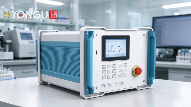
Start with dimensions and tolerances that survive the supply chain. A bench instrument like the F03 medical housing (275 × 151.85 mm body) typically uses an extruded body with CNC-machined end caps: extrusion cross-sections hold ±0.1–0.2 mm, machined faces hold ±0.05 mm, and overall length ±0.3–0.5 mm. Wall thickness guidance: 1.5–2.0 mm for extruded enclosures up to 300 mm long, 2.0–3.0 mm for larger spans; sheet-metal wrappers use 1.5 mm (16 ga) for panels and 2.0 mm (14 ga) for load-bearing brackets. Weight and center of gravity matter for portable testers — keep the heaviest sub-assembly over the base and state the finished-unit CG on the drawing.
Internal layout is where most suppliers stop short. Define PCB support points explicitly: standoffs on a 60–100 mm pitch for 1.6 mm boards, M2.5 or M3 countersunk screws at the four corners plus mid-span, and a separate mounting zone for transformers or pumps. Port cutouts need released drill/DXF templates — display, keypad, USB and mains openings — so the factory cuts them once, correctly. Route power and signal in separate internal channels with a defined isolation gap, and decide rack vs desktop early — a 19-inch rack face adds ±0.2 mm width requirements and mounting ears, while desktop units (F03-style with front handles) need rear rubber feet and tilt clearance. The F-series, G-series instrument boxes and B-series chassis catalog removable top, base and rear panels so boards drop in from two axes; ask YONGU for the STEP/assembly package and drill templates to verify your board fit before tooling.
Thermal Dissipation and Thermal Management Strategies
Design thermal paths in order: conduction first, convection second, forced air last. Aluminum conducts 4–10× better than plastic, so the default path is PCB → baseplate or wall via thermal pads (1–6 W/m·K), then spread to the enclosure surface. For a bench medical tester, a body with 0.15–0.3 m² of surface dissipates roughly 10 W per m² per °C by free convection — enough for 20–50 W of internal loss in a 22–25°C lab, with 10–15°C margin before the skin gets warm.
Above that budget, add filtered ventilation before fans — a passive vent stack with a washable filter handles 20–40 W, then fit an axial fan sized at 30–60 CFM per 100 W of heat with 30–80 Pa backpressure; quieter matters in clinics. Fan filters need a maintenance plan: inspect quarterly and replace annually, and document the acoustic level (target <45 dB(A) at 1 m in patient-adjacent rooms). Heat pipes or heat sinks become worthwhile only when hotspots exceed the spreading ability of a 2 mm aluminum wall. Include a per-module thermal budget in your spec — each PCB's watts, allowed rise, TIM — so the enclosure is sized from data, not guesswork. For sealed deployments, filterless vent caps or heat-pipe bridges to an external heat sink avoid fan dust. Verify with a chamber soak at rated load, logging skin and internal air temperature against the budget — 60 minutes is a practical minimum. The F03's side vent grilles and removable panels support exactly this passive-first design; the testing-instrument enclosure guide shows a similar thermal path in production.
EMI/RFI Shielding, Grounding and ESD Protection
A machined aluminum chassis is a Faraday cage only if the openings are disciplined. Keep every seam gap and cutout smaller than roughly λ/20 of the highest frequency of interest — about 15 mm at 1 GHz — which is satisfied by flanged covers with conductive gaskets on the long seams and gasketed glands at every cable entry. Specify nickel- or tin-plated beryllium copper gaskets, or conductive foam where compression is limited, with 10–20% compression set and a planned life of 5+ years; periodic re-torque of cover screws (M3 at ~0.6 N·m, M4 at ~1.2 N·m) maintains the shield over time. Filter or shield every feedthrough — mains, USB, display ribbon — at the wall, because a clean enclosure defeats its purpose if the cable acts as an antenna.
Grounding should be explicit, not incidental. Use a hybrid scheme: a low-impedance ground bus along the baseplate (copper bar or plated rail) bonded to the chassis at the power entry, single-point grounding for analog and patient-adjacent circuits to avoid loops, and braided straps across hinges so covers stay at chassis potential. Mark the ground stud on the drawing and specify the torque. For patient-connected circuits, IEC 60601-1-2 EMC requirements and 2 MOPP isolation rules apply — keep isolation barriers away from the shield ground, and design to the RF immunity and ESD test levels early rather than retrofitting. The precision medical enclosure guide and the medical device enclosure guide cover the compliance workflow from layout to test.
Regulatory Compliance, Sterilization Compatibility and Cleanability
Medical programs require documentation, not promises. Expect the chassis supplier to deliver, with each batch: an ISO 13485 system statement or audit evidence, material certificates (alloy and temper), RoHS and REACH declarations, and traceable batch/lot numbers on the drawing or label. For FDA-tracked products, keep a documented change record for every revision of the housing — the enclosure is part of the device master record. YONGU supplies ROHS/REACH declarations and independent test reports on the downloads page and supports laser-engraved batch marking on the F03 and other series.
Cleaning and disinfection drive finish selection. Anodized aluminum (sealed Type II) tolerates the common hospital wipe-downs — 70% isopropyl alcohol, diluted bleach, and hydrogen peroxide wipes — without cosmetic damage; powder coat is similar but can dull under aggressive bleach; stainless panels are the choice for repeated high-level disinfection. Autoclave temperatures (121–134°C) are structurally acceptable for aluminum, but repeated cycles degrade anodize, gaskets and adhesives — if your instrument is autoclaved, specify stainless surfaces and validated cycle counts, or design the sterilizable parts as removable. Hydrogen-peroxide vapor and low-temperature plasma are generally safe for anodized aluminum. Cleanability is a design feature: avoid crevices and dead corners, radius internal edges, and make filters and vent panels removable without tools. The instrument enclosure guide lists the cleanability checks to put on your validation protocol.
Customization, Prototyping, CAD Assets, Lead Times and Production Considerations
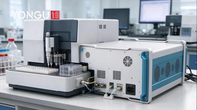
Choose the manufacturing route by volume and tolerance. Extruded bodies (F03/B-series style) amortize a die over quantity — dies and fixtures are the main NRE — then CNC and surface finishing dominate the unit cost; sheet-metal wrappers avoid extrusion tooling and suit short runs but hold looser tolerances (±0.2–0.5 mm) and need welding/forming care. CNC machining tolerances at YONGU run about ±0.05 mm, laser cutting about ±0.1 mm, which is ample for instrument panels. Typical project timeline: prototype 5–7 days, small batch 2–4 weeks, production 4–8 weeks, with a minimum order of one unit — prototype cost buys the design verification; production price then drops with quantity and fixture amortization. Ask for a quote broken into material, machining, finishing, hardware and NRE so change requests are priced, not absorbed.
Deliverables should be engineering-grade: STEP/CAD models, assembly drawings, and drill templates released under NDA, plus a packing and transport standard — foam inserts and corner guards validated by a basic ISTA-style drop sequence (edge, corner and flat at 60–80 cm) and a 5–100 Hz vibration sweep at 0.5–1 g before mass shipment. The F03's anodizing options, hole-drilling customization and laser-engraved marking cover branding and certification marks; the customization guide and enclosure selection guide walk through the decision sequence, and YONGU supports NDA-gated engineering review before any tooling or NRE commitment.
Conversion
Move your medical instrument project forward: request a custom quote, download the STEP/CAD package and drill templates, or book an engineering review with YONGU — responses typically arrive within 24–48 hours, and NDA-gated controlled documentation is available for regulated programs. Deliverables include functional prototypes, EMC test reports, material and finish samples, and ISO 13485-consistent documentation support; lead times run 5–7 days for samples and 15–20 days for batch production, with expedited manufacturing and compliance-document assistance for U.S. buyers. Send your board stack-up, thermal budget and target certification to contact YONGU and get a chassis engineered for your instrument, not adapted from a generic box.
FAQs
What mechanical tolerances and sheet metal thicknesses are recommended for aluminum chassis in medical testing equipment?
Extruded bodies hold ±0.1–0.2 mm cross-section with CNC faces at ±0.05 mm; sheet metal holds ±0.2–0.5 mm (laser ±0.1 mm). Use 1.5–2.0 mm walls for extruded enclosures up to 300 mm and 2.0–3.0 mm for larger spans; 1.5 mm (16 ga) panels and 2.0 mm (14 ga) brackets for sheet-metal builds.
How should I design thermal dissipation for enclosed medical test instruments while keeping them cleanable?
Conduction first — thermal pads to the aluminum wall — then filtered passive vents, then axial fans at 30–60 CFM per 100 W with <45 dB(A) targets. Keep filters tool-free removable for cleaning, and size from a per-module thermal budget with 10–15°C margin in a controlled lab.
What EMI/RFI shielding and grounding practices are required for medical instrument enclosures?
Keep seams and openings below ~λ/20 of the highest frequency (≈15 mm at 1 GHz), use conductive gaskets with 10–20% compression, filter every feedthrough, and ground via a low-impedance bus with single-point grounding for analog and patient-adjacent circuits per IEC 60601-1-2.
Which sterilization and disinfection methods are compatible with aluminum chassis and common finishes?
Anodized aluminum tolerates IPA, diluted bleach and hydrogen peroxide wipes plus H2O2 vapor; powder coat is similar but can dull under aggressive bleach. Autoclave temperatures are structurally acceptable, but repeated cycles degrade anodize and gaskets — specify stainless for autoclaved parts.
What regulatory documentation should chassis manufacturers supply for medical testing equipment?
ISO 13485 system evidence, material certificates, RoHS/REACH declarations, traceable batch numbers, and a documented change record for FDA-tracked programs. YONGU supplies ROHS/REACH declarations and test reports with each batch.
What are typical lead times, prototyping costs, and minimum order quantities for custom medical-grade aluminum chassis?
Prototypes run 5–7 days and small batches 2–4 weeks, with MOQ of one unit. Cost splits into material, machining, finishing, hardware and NRE; production pricing drops as fixtures amortize across quantity.
Are CAD/STEP files, drill templates and mechanical drawings usually provided for custom builds?
Yes — YONGU releases STEP/CAD models, assembly drawings and drill/DXF templates under NDA for engineering verification before tooling, so board fit and port openings are checked before any commitment.