A heatsink rack mount enclosure is a 19-inch rack-mount housing whose aluminum body doubles as a heat dissipator — extruded or machined fins on the top, sides, and rear conduct heat out of power-dense modules instead of trapping it. For amplifiers, industrial PCs, servers, and test equipment in a rack, the enclosure is not a box around the electronics; it is the thermal system. This guide turns thermal management into numbers an engineering team can spec against: thermal resistance targets, airflow and fan selection, heat sink and TIM choices, CFD validation, and the serviceability and compliance checks that keep a rack reliable in the field.
Thermal Performance Targets and Power Density Limits
Start from the silicon and work outward. The junction-to-ambient budget is RθJA = (Tj,max − Ta) ÷ P, where Tj,max is the device junction limit, Ta is the inlet ambient, and P is the dissipated power. Example: a 60 W module with Tj,max = 105 °C in a 40 °C rack gives RθJA = 65 ÷ 60 ≈ 1.08 °C/W. Subtract the package resistance RθJC (typically 0.15–0.3 °C/W for power packages, per datasheet and JEDEC JESD51 measurement methods), and the enclosure-plus-heatsink system must deliver RθCA ≈ 0.7–0.9 °C/W — a concrete target, not a guess.
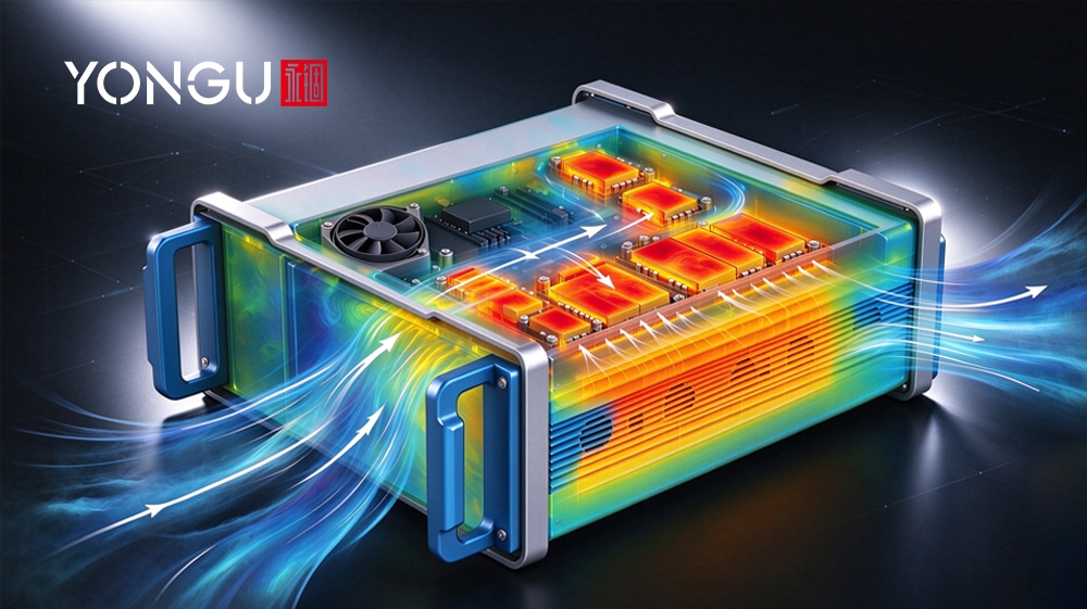
Translate that into rack density. In a 1 U (44.45 mm) aluminum enclosure roughly 300–500 mm deep, natural convection with finned walls handles about 5–15 W/U; with a ducted fan it rises to 30–100 W/U depending on fin area, airflow, and inlet temperature. Two design margins prevent field surprises: size for 20–30% headroom at steady state, and check transient peaks against thermal mass — aluminum's specific heat of about 897 J/kg·K lets a 1 kg body absorb roughly 27 J per °C of rise, which smooths 5–10 s spikes that steady-state math over-rates. For pulsed loads, use RMS-equivalent power for the continuous target and verify the peak separately. The YONGU heatsink rack mount enclosure F01 (275 × 107.4 mm, ~2 U) shows how the target is reached in practice: finned side panels, a rear fan position with vent grilles, and removable top, base, and rear plates for internal airflow work. Why aluminum carries this duty so well is covered in our aluminum thermal conductivity guide.
Airflow Path Design, Fan Selection, and Acoustic Management
Airflow is the second lever, and it must be designed as a path, not assumed. Lay out front-to-back flow (inlet on the front panel, exhaust at the rear), seal bypasses between modules so air does not recirculate, and budget pressure drop: each vent grille, filter, and fin array consumes static pressure, and a fan that is mismatched to the duct will move far less than its free-air CFM. A practical sizing formula is CFM ≈ 3.16 × watts ÷ ΔT(°F). For 60 W with a 15 °C (27 °F) rise, that is about 7 CFM through the enclosure — the fan curve must deliver that flow at the duct's operating pressure, so pick a high-static-pressure fan (40–60 mm dual ball bearing, 3–10 mmH₂O class) and read the fan P-Q and system resistance curve intersection, not the free-air rating.
Control the fan with a PWM curve rather than on/off: start at ~20% duty below 40 °C, ramp to 100% by 55–60 °C, with 3–5 °C hysteresis to prevent hunting. Set acoustic targets early — under 45 dBA where quiet matters, up to 55–60 dBA in industrial rooms — and prefer larger slow fans over smaller fast ones at equal flow, add anti-vibration mounts and soft fan frames, and cap the top speed in firmware unless thermals demand more. Design the failure chain too: N+1 fan redundancy, and a degraded mode that raises fan speed, then reduces power, then alarms, so a single fan loss never cooks the load. The finned-body approach of the F-series is explained in our heat sink enclosure guide.
Heat Sink Selection, Thermal Interface Materials, and Mechanical Integration
For rack modules, the heat sink is usually integrated with the enclosure: extruded aluminum profiles (6063-T5, conductivity ≈ 200 W/m·K; 6061-T6 ≈ 167 W/m·K) with fin spacing of 3–6 mm for natural convection or 1.5–3 mm for ducted airflow, fins oriented along the flow direction, and a machined base plate that seats the PCB or power devices. Skived or bonded-finned assemblies add area where extrusion geometry cannot, at a cost premium; a fully machined body (like the F01's finned side walls) is the middle path for custom rack lengths. Trade heat sink options on three axes: thermal resistance per cost, weight per rack unit, and manufacturability of the fin geometry (minimum fin thickness, draft, and tooling for extrusions).
| TIM type | Typical conductivity | Serviceability | Best for |
| Thermal grease | 0.5–8 W/m·K | Re-workable, needs clean-up | Permanent modules, thin bond lines |
| Thermal pad | 1–6 W/m·K | Reusable, forgiving height tolerance | Field-swappable modules, gap filling |
| Phase-change material | 3–8 W/m·K after melt-in | Re-mountable once cured | High-pressure flat interfaces |
| Cured adhesive | 1–3 W/m·K | Permanent bond only | Devices fixed for life, vibration-prone |
Mechanical integration decides whether the TIM actually works. Specify a machined, flat mounting face (surface flatness and roughness controlled in the same CNC setup as the cutouts), a defined bond line thickness, and preload through captive screws — M3 at roughly 0.5–0.7 N·m with spring washers for repeatable seating. For hot-swap modules, choose pads or phase-change materials that tolerate repeated assembly, keep spare interfaces clean, and mark the re-torque interval. Design tips for enclosure-integrated sinks are in our aluminum heat sink PCB design guide.
Thermal Simulation (CFD) and Validation Testing
Model before you build, then prove the model. Set CFD boundary conditions from the real system: inlet temperature (e.g., 35 °C rack ambient), the fan's P-Q curve instead of free-air CFM, and element-level power distribution from the electrical design. Mesh the fin gaps with at least three cells across each channel and resolve the boundary layer near fins and devices; run steady-state for the continuous rating and a transient case for peak loading, since aluminum's thermal inertia hides in steady-state results. Include radiation — anodized aluminum's high emissivity (roughly 0.8–0.9) carries a meaningful share of natural-convection cooling, unlike bare polished metal — and model vent openings with the real grille pattern, not free boundaries.
Validate on hardware with a defined protocol: place thermocouples at inlet, outlet, device case, and heat sink base; capture a thermal map with an IR camera; and soak in an environmental chamber at 25, 35, and 40 °C at full load. Acceptance criteria should be numeric and agreed upfront — junction/case temperature at or under spec at the highest ambient, and CFD-versus-test correlation within about ±10% on the critical points — then the simulation becomes a usable prediction tool for variants. A worked example of modeling aluminum alloy chassis for thermal and signal duty is in our aluminum chassis thermal design guide.
Serviceability, Monitoring, Redundancy, Failure Modes, and Compliance
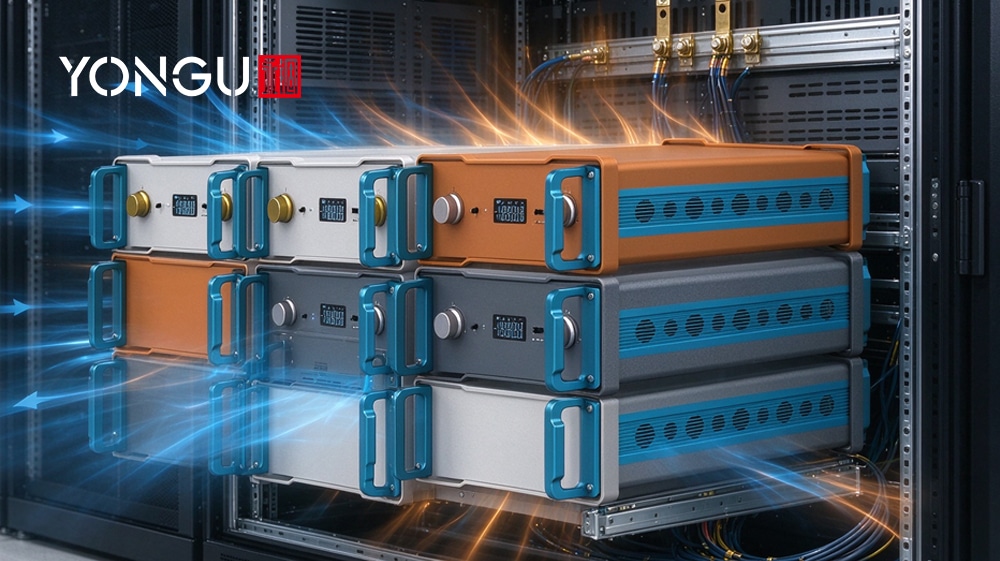
Field reliability is designed in at the enclosure level. For hot-swap modules, provide temporary cooling — adjacent fan airflow or a low-power standby mode — so pulling one module does not spike its neighbors; make fan modules themselves hot-swappable with blind-mate connectors and tach feedback. Common failure modes and their mitigations: fan bearing or stall failure (covered by N+1 redundancy plus a tach alarm), filter clogging (pressure-drop or temperature-delta alarms, quarterly inspection), TIM pump-out or aging (re-torque schedule, re-apply at service), and blocked vents (the F01's "do not block the vent" marking is exactly this design rule). Place sensors where they predict failures: exhaust air temperature, heat sink base temperature, and per-fan tach; alarm on absolute exhaust temperature and on inlet-to-outlet delta, which catches filter and fan degradation before the load overheats.
Compliance frames the design from the start. For U.S. rack equipment, radiated and conducted emissions fall under FCC Part 15 (47 CFR Part 15) — a closed metal enclosure with gasketed seams and shielded vent openings is the primary mitigation — and safety follows UL 62368-1 (fourth edition, published July 2025), which covers temperature rise, guarding of fans and openings, and fire enclosure requirements. Add a production-line thermal check — powered burn-in at nominal load with a pass/fail temperature reading and fan current check — so field units match the validated design. Rack system context is covered in our 19-inch rack guide and rack mount enclosure overview. Specify UL 94-rated plastics, finger-guard fan openings, and verify ground continuity and fan current during production burn-in so field units match the validated design.
Conversion
Get a thermal design review for your rack module. Send us your power distribution, rack dimensions, and noise and redundancy targets, and YONGU will return an Rθ budget calculation, a CFD grid and boundary file set, or a prototype thermal test — an initial review within 1–2 working days, a CFD report in 3–5 working days, and prototype hardware in 5–7 days, with no minimum order. The F series heatsink enclosures and the custom CNC enclosure program accept custom lengths, cutouts, and fin layouts; drawings in STEP/CAD/DXF are supported, and test reports and certifications are on the downloads page. Start the review through the contact page. Custom fin layouts, gasketed vent covers, and redundant fan bays are designed in at the drawing stage.
FAQs
How do I calculate the required heat sink thermal resistance for a rack-mounted module?
Use RθJA = (Tj,max − Ta) ÷ P for the full junction-to-ambient budget, subtract the package resistance RθJC from the datasheet, and the remainder is the required case-to-ambient resistance RθCA that the heat sink and airflow must provide. Example: 60 W, Tj,max 105 °C, Ta 40 °C gives RθJA ≈ 1.08 °C/W, leaving roughly 0.7–0.9 °C/W for the sink.
What are the best practices for CFD modelling of airflow inside a 19-inch heatsink enclosure?
Use real boundary conditions — inlet ambient, the fan P-Q curve, element-level power — mesh fin channels with at least three cells across, run steady-state plus a transient peak case, model radiation from anodized surfaces, and validate against thermocouple and IR measurements within about ±10% before trusting the model for variants. Judge convergence by stabilized residuals and monitored point temperatures, not iteration count alone.
Which thermal interface materials work best for high-power removable rack modules?
For field-swappable modules, use thermal pads (1–6 W/m·K) or phase-change materials, which tolerate repeated assembly; reserve grease for permanent thin bond lines and cured adhesives for life-fixed, vibration-prone joints. Control bond line thickness and preload (M3 at ~0.5–0.7 N·m) so the interface performs as designed.
How should I size fans and program control curves for cooling, redundancy, and acoustics?
Size airflow with CFM ≈ 3.16 × watts ÷ ΔT(°F) and select a fan whose P-Q curve delivers that flow at the duct's pressure drop. Control with a PWM curve ramping from ~20% below 40 °C to 100% by 55–60 °C with hysteresis, cap speed for acoustics (under 45 dBA where quiet matters), and provide N+1 redundancy with a degraded-mode response.
What sensor placements and validation tests prove an enclosure meets thermal requirements?
Place sensors at exhaust air, heat sink base, and per-fan tach; alarm on absolute exhaust temperature and inlet-to-outlet delta. Validate with thermocouples, an IR thermal map, and a chamber soak at 25/35/40 °C at full load, with pass criteria agreed before testing.
How do hot-swap, redundancy, and FCC/UL compliance affect the mechanical design?
Hot-swap needs temporary cooling paths and blind-mate fan modules; redundancy needs fan slots, tach wiring, and degraded-mode logic. FCC Part 15 pushes gasketed seams and shielded vents, and UL 62368-1 (4th edition) governs temperature rise, fan guarding, and fire enclosure — so airflow, vent geometry, and grounding are decided together, not sequentially.