- Remuneration during process
- Enhanced Functionality
- Diagnostic
- Machine Tool Control
INTRODUCTION TO CNC MACHINES WORKING
A computer and CAM program employs digital data to automate and control a machine's motions. The computer is usually a specialized onboard controller for more extensive industrial machinery. However, an external PC can be used for amateur devices or retrofits. The CNC control system uses a set of actuators and drives to control and move the machine axes. The cutter's speed and position are continually monitored and adjusted by a comprehensive feedback system on industrial equipment.
Desktop CNC Machines - These machines can perform well for softer materials like plastics, foams, and wax, While this may be true, the advantages of consumer-grade devices outweigh the disadvantages of industrial-grade ones in terms of weight, rigidity, accuracy, speed, and cost. Some desktop computers may function more like printers than computers. Others use a proprietary command system and may even use CAM software only available to them. Some G-code can also be used as input. Dedicated controllers for accurate small-scale tasks are available on several industrial-standard desktop workstations.
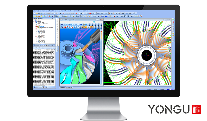
Computer-Aided Manufacturing - To run a CNC-controlled machine, toolpaths and NC code must be generated from 3D computer model data using various software programs.
It is not the CNC machine that is controlled by CAM but rather the code that CAM generates for it to obey. Also, importing your CAD model and developing the appropriate NC code is not automated. Even while novices can get started with simple programs, more experienced users will need to invest time and money to learn how to utilize more complex models.
NC code – CNC machines can understand and execute a specialized computer language. A CAM software wasn't necessary because these languages were initially designed to be programmed directly on an industrial machine's keyboard. Additionally, they are responsible for managing other machine operations, including spindle and feed speeds, coolant flow, and other parameters. G-code is the most often used alphanumeric programming language that was developed in the 1970's.
Post Processor - All manufacturers can alter sections like auxiliary functions of G-code so that it can only operate on particular machines it is designed for. Additionally, a large number of machine manufacturers have created proprietary programming languages of their own. A software component known as a post processor acts as a bridge, allowing the CAM program's internally determining routes to be converted into particular NC code for CNC machine to interpret and operate.
LIMITATIONS OF CNC CONTROLLED MACHINES
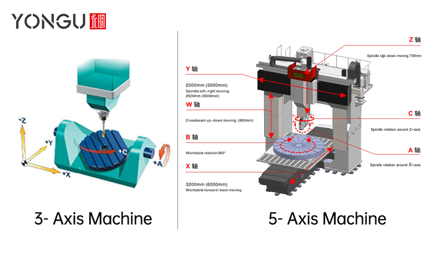
Multiple axes of movement are possible with CNC machines, and these movements can either be linear or rotational. Both sorts of machinery are common. X and Y are the only two linear axes on most cutout machines, such as lasers or waterjets. A milling machine's X, Y, and Z axes are the most common; however, more rotating axes are possible. A 5-axis milling machine is one that has three linear axes in addition to the two rotating axes. This allows the cutter to operate in a hemisphere that is 180 degrees or greater in diameter. There are other lasers with five axes of rotation. There may be more than five axes on a robot arm.
The controller of CNC machines, depending on how old they are and how much complexity they have, can often be restrictive. For the most part, CNC machines can only move in straight lines or circular arcs. In addition to this, the arcs of many machines are constrained to the primary XYZ planes. The movement of a rotating axis can be thought of as a linear movement, with the exception that degrees are measured rather than distance. Interpolation between two or more axes is required in order to produce arc motions or linear motions that are at an angle to the major axes. It is also possible to interpolate on both linear and rotational axes at the same time. When it comes to five-axis machines, it's not a simple chore to keep them all in sync.

INTERPRETATION FOR CAM PROGRAMMING
File building and CAM programming are two of the most typical issues people face while working with CNC machines. Non-arc shapes must be changed to be recognized by most CNC controllers, which only recognize arcs and lines. 3D surfaces, spline curves, and non-arc curves are frequently converted. Not all desktop PCs support circular arcs; thus, everything is converted to polylines.
It is possible to break splines into line segments or tangent arcs; however, this isn't always the case. You may begin by creating a spline of chords that contact at the ends and deviate in the middle. A spline-to-polyline conversion option is also an option. The approximation is rougher and more faceted, using fewer segments. The smoother the approximation, the more details there are. Using longer arcs may bring your spline within acceptable margins of error. 'Spline' If you're using an older computer, it's better to use arc conversion rather than polyline conversion—less of a problem with newer models.
Surfaces may be seen as spline approximations multiplied with gaps between them. When creating a surface, line segments are often used; however, arcs or a combination of the two can also be employed.

Segments are affected by accuracy and approach, which in turn influences execution. It's impossible to create faceted pieces on earlier machines because there are too many short segments and not enough. In CAM, this is a widespread practice. A knowledgeable operator familiar with the equipment's capabilities will often have no issues. To use CAM, you may need to convert splines or other surfaces in Rhino first. Problems might arise while moving from CAD to CAM because of the programs' import/export features.
CNC MACHINING CENTER
A CNC Machining Center may be described as a machine that combines the functions of many machines. The CNC Machining Center may perform many different machining functions. It decreases machine downtime and enhances production efficiency by using one-stop manufacturing.
Because it is computer-controlled, it is possible to carry out a wide variety of machining operations with the highest possible levels of precision, quality, and dimensional accuracy.
MECHANISM TYPE OF CNC MACHINING CENTER
Cutting down on manufacturing time and using modern mechanisms are the primary goals of the CNC machine center.
- Servo System
- Feedback system
- Automatic Tool & Pallet Changer
- Re-Circulation System
- Horizontal Machining Center
- Vertical Machining Center
- Universal Machine Center
Now, every CNC machine requires machining cases to fulfill the requirements of international laws and protect their machines from outside dangers, including water protection, dust protection, and many others, so YONGU presents specially designed cases for CNC machines.

YONGU Aluminium CNC Machining Enclosure
The YONGU B Series CNC Machine cases contribute while designing the CNC machines as they have their benefits when merged with CNC machines which are to be used in every industry. YONGU provides customers with the ability to customize enclosures in all three dimensions.
YONGU Custom Instrument Cabinet Industrial Control Chassis B05 358*2U mm
CNC Enclosures made by YONGU provide several advantages in the production process.
- Aluminum CNC Machining Case
- Customizable thickened panels with precision processing
- Strong load-bearing capacity
- Easy Installation
- Heat dissipation is built into the side plates of the enclosure, which improves the function of heat dissipation and lends an air of elegance to the cabinet's essentially pragmatic and industrially designed appearance.
- The front, rear, side handles, and side corners are all CNC processed to give you a technological sensation.
- Inner plates can reduce the fixing problems such as screws and rivets on the surface.
- The length, breadth, and height may all be adjusted. The length may be extended or lowered in increments of 50mm or 100mm as one unit.
- Customizable dimensions, cutout, colors, printing, etc.
- Screws use unique models to enhance your equipment safety.
- The rubber foot pads can be slip-proof and moisture-proof and have a protective effect on internal components.
For further information and customized product of your requirements, please follow our FACEBOOK for more updates and informations: https://www.facebook.com/Foshan-Gof-Electronic-Machine-Co-Ltd-104706631749290
You can also contact us at +86 13326782625 or write us [email protected].


